The myPhone v2.0 project
Overview
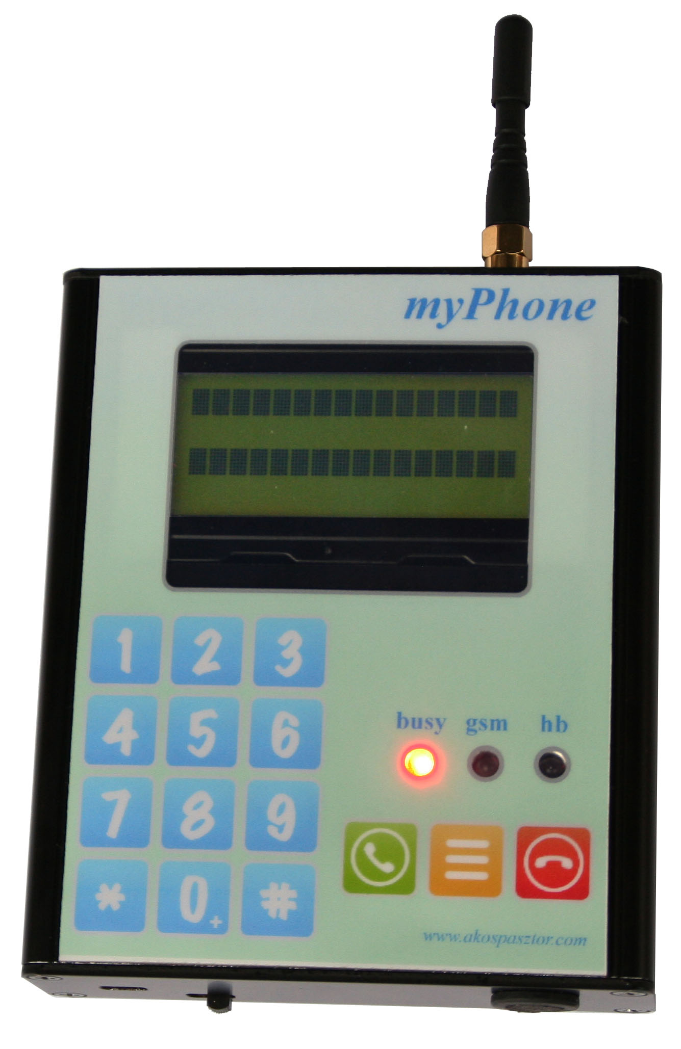
There are two versions of this device. The v1.0 version has no case, the keyboard is on the main PCB, and this version has no battery. However this version is fully-functional, it has some minor problems: the keyboard handling is difficult (there are no button-labels and the level of the keys are much lower than the top of the phone), and you cannot carry a big power supply with you all the time… So I decided to make a new version. The v2.0 version has an aluminium enclosure with a keyboard on the top, and there are two batteries inside which can be charged via USB. This version deserves the “phone” name because the v2.0 version is portable: you can use it without any cable or accessory. Below you can read about the building steps of the myPhone v2.0.
View documentation (Hungarian)
Contents
- Overview
- Contents
- Functions
- Components
- Schematics
- Layout
- Manufacturing
- Soldering
- Enclosure
- Assembled hardware
- Software
- Video
Functions
The module can connect to the GSM network, and the user can launch and receive calls. It has a memory for storing contacts and numbers which can be downloaded into the device from a computer through USB port. On the display the user can see the actual state of the phone: service name, signal strength, date & time and battery info.
- The myPhone can launch calls
- The myPhone can receive & answer (or deny) incoming calls
- Phone-book: there is an EEPROM for storing contacts
- The phone-book is downloadable from a computer via USB port
- Battery management: two rechargeable batteries for power supply, which can be charged via USB port
- Step-up converter to produce 5V for the components
- 4x16 LCD display with backlit & adjustable contrast
- Loud speaker with 1W amplifier
- Sensitive microphone
Components
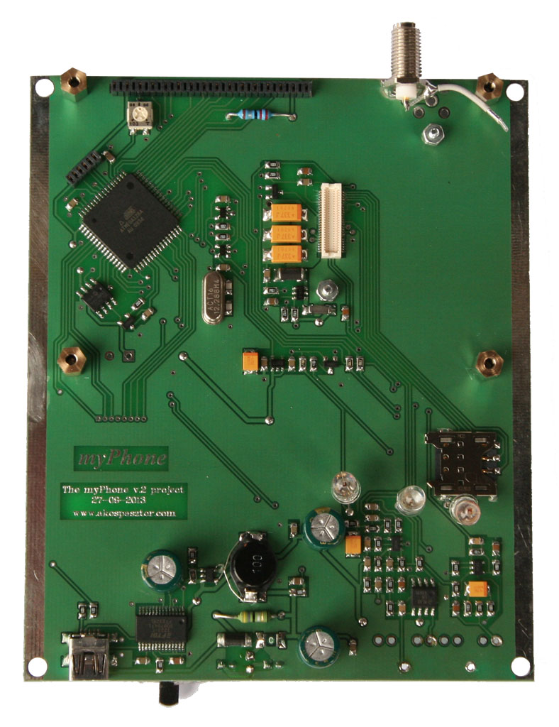
The myPhone is driven by an AVR AtMega128 microcontroller. The whole device consists of 2 PCB-s. One mainboard with the components inside the case, and one thin pcb containing the push-buttons on the top of the case.
On the mainboard:
- Atmel AtMega128 microcontroller with 12.288MHz clock frequency
- J-TAG interface for programming & debugging
- HUAWEI EM310 GSM module with micro-SIM card holder & external aerial
- DEM 16481 SYH-LY 4x16 LCD display with backlit & adjustable contrast (with HD44780 compatible controller)
- 512Kbit SPI EEPROM for storing the contacts and numbers (max. ~1000 contacts)
- MP3410 step-up converter to produce 5V
- LP2985 step-down converter to produce 3.3V needed by the GSM module for UART communication
- 74LVC1G07 non-inverting buffer needed by the GSM modue for UART communication
- FT232RL UART to USB converter for the USB communication with mini-USB port
- MCP601 pre-amplifier for the microphone and the loud speaker
- LM4861 1W audio power amplifier with shutdown mode for the loud speaker
- MCP130 reset IC
- LEDs to indicate the status of the device
- Li-polimer batteries - 2 x 2450mAh
- MCE-100 9.7mm electret microphone
- Slim design 8Ohm 26W loud speaker
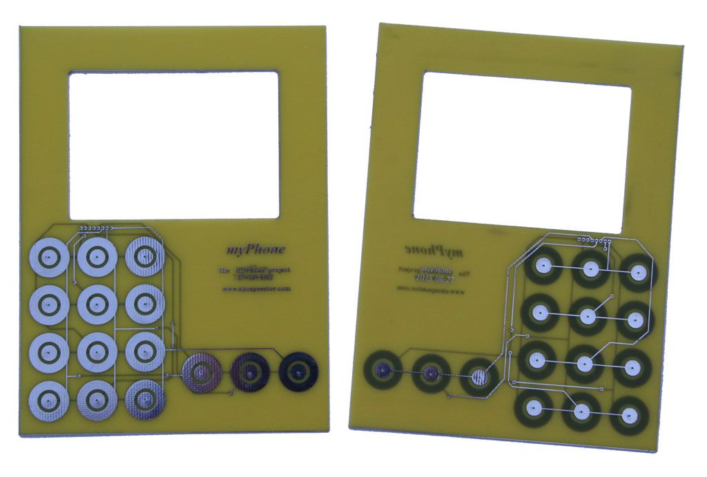
On the top:
- Custom designed foil keyboard with PCB base
- Graphics & cutouts
- 15 push-buttons
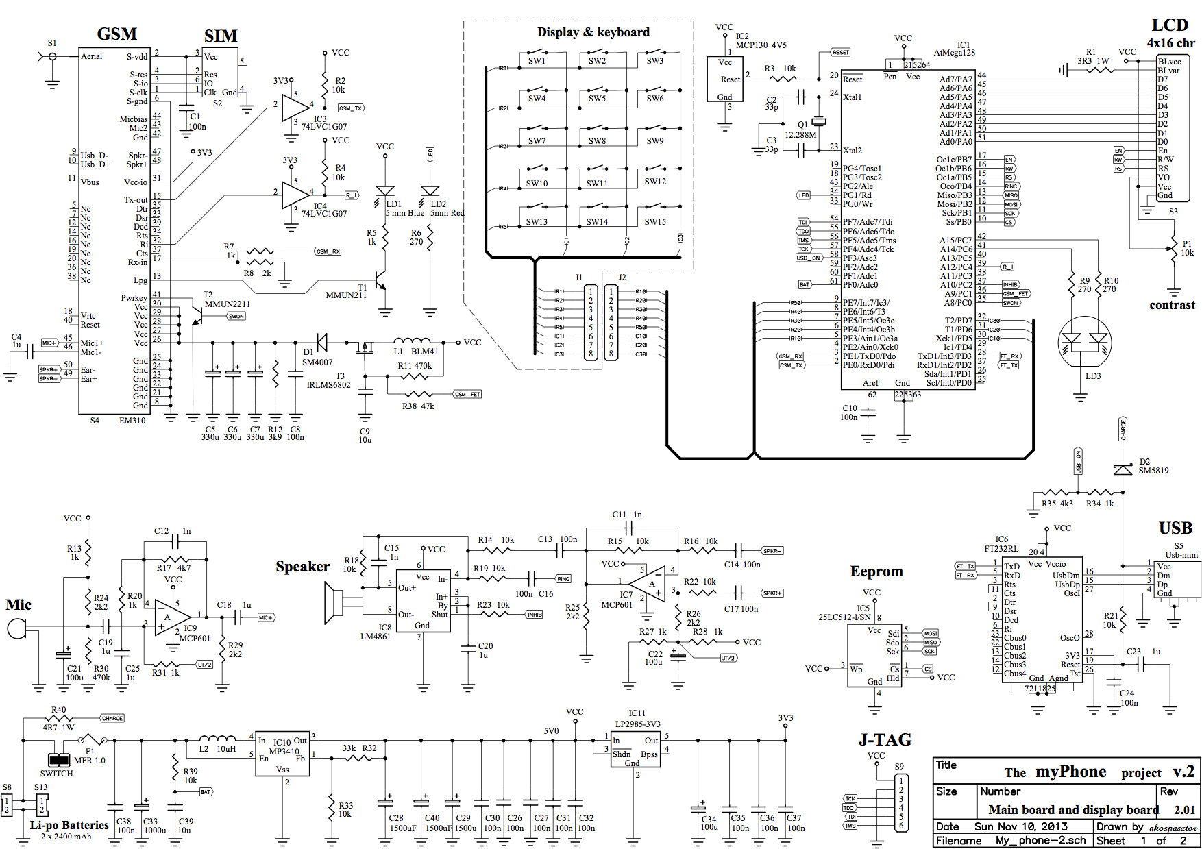
Schematics
I made the schematics with P-CAD software.
Note: You can download it as a PDF!
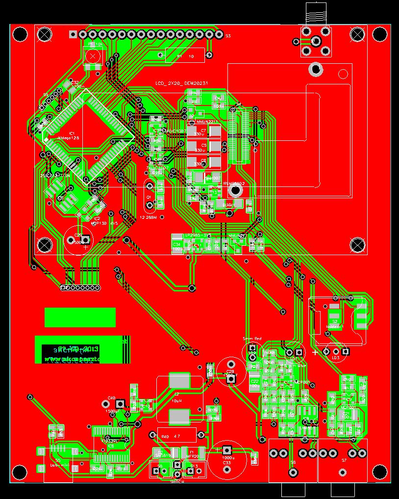
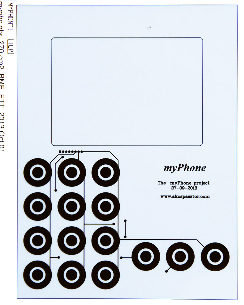
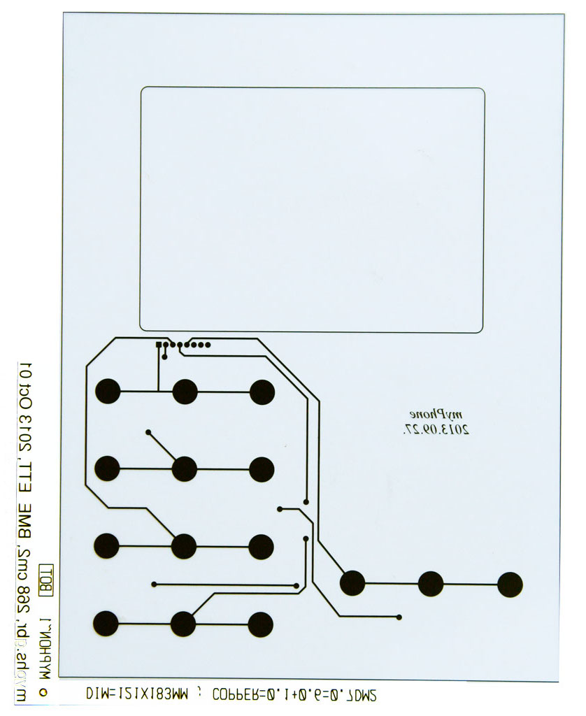
Layout
I also used the P-CAD software for creating the layouts from the schematics. Here are some screenshots:

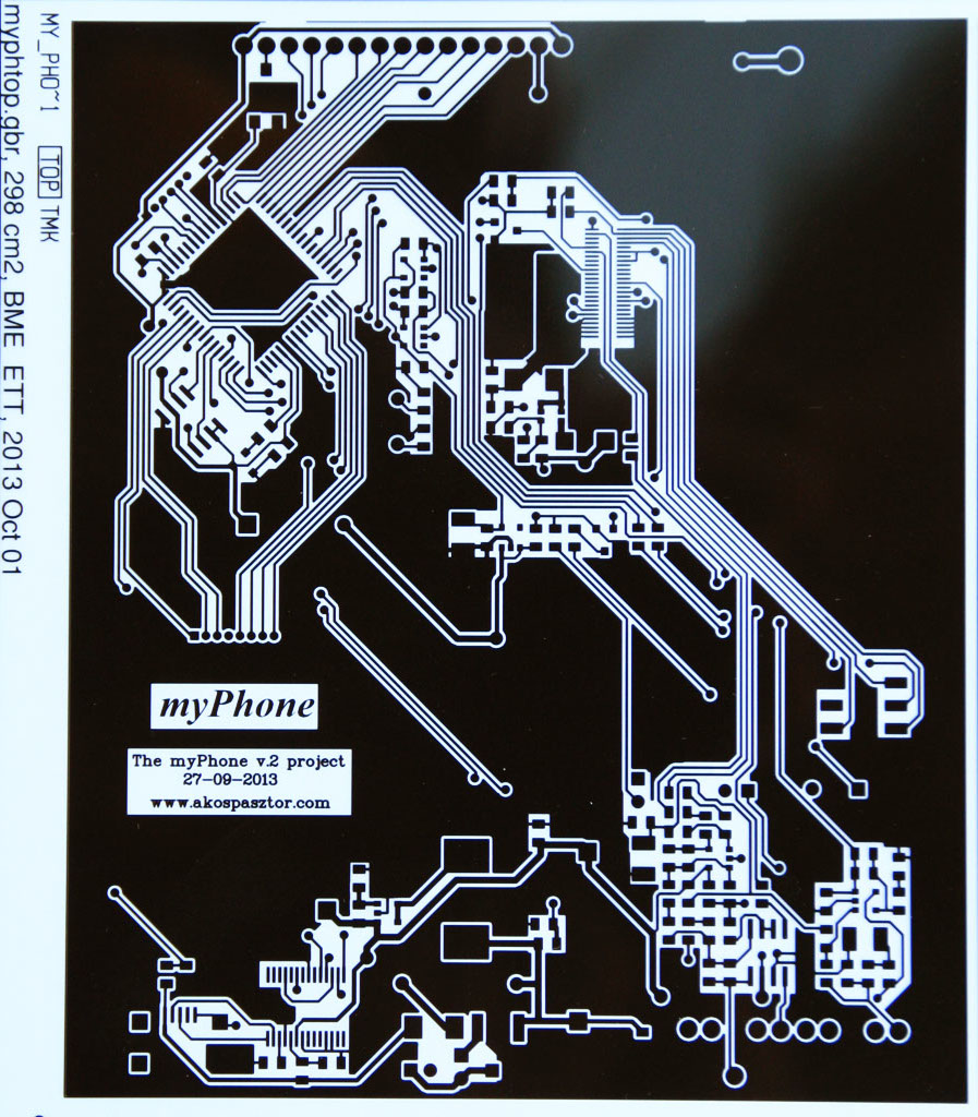
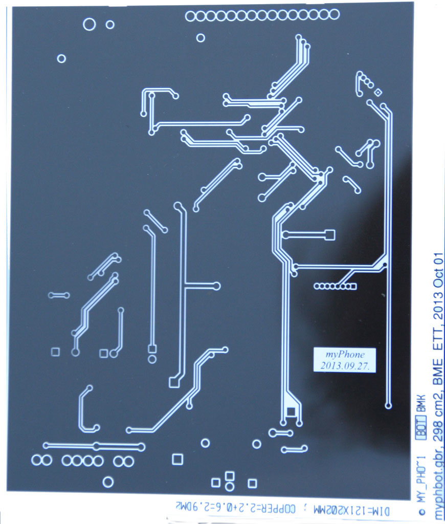
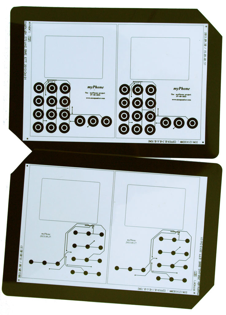
Manufacturing
The PCB’s were manufactured at the Department of Electronics Technology (ETT) of Budapest University of Technologies (BME). Here are some photos of the films that needed to the manufacturing process.

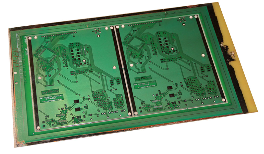
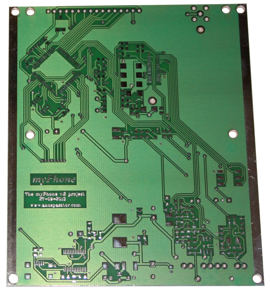
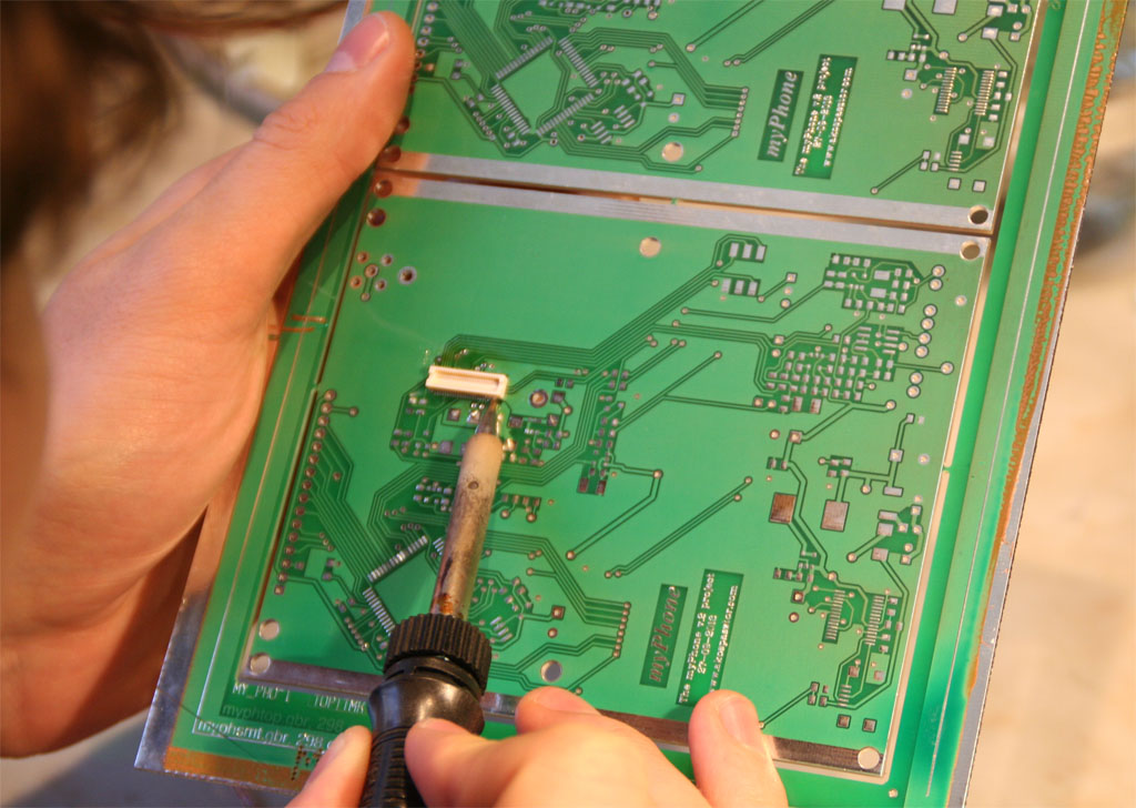
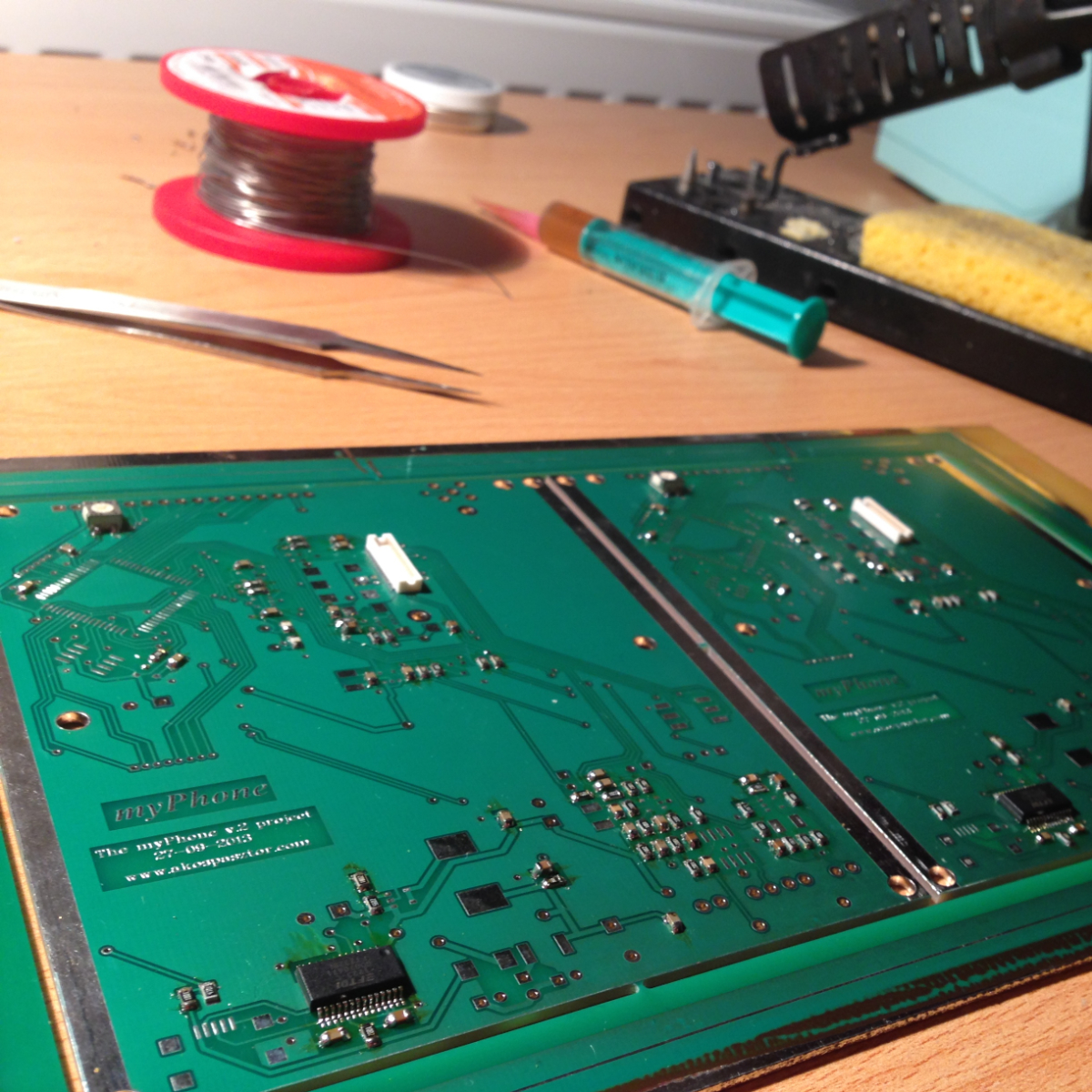
Soldering
All components are soldered by myself by hand. I used a Weller WS-80 soldering set. Most components were soldered with Stannol Kristall 505 0.5mm with 3.0% flux soldering wire, and I used Ersa F-SW 32 fluxpaste where needed. The 10/10 mils molex connectors for the GSM sweated me but the other SMD and thru-hole components could be soldered in without difficulity. Here are some pics about the PCB-s and the process.

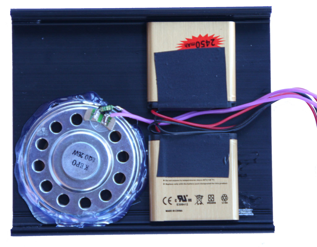
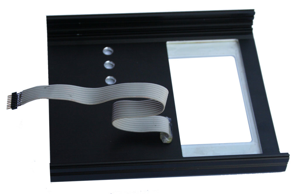
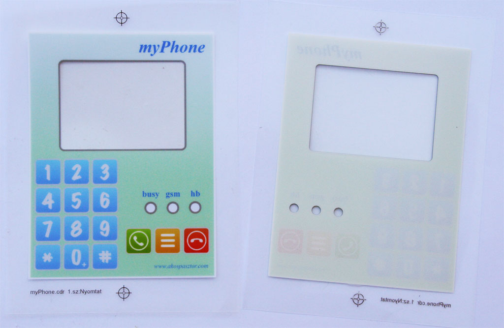
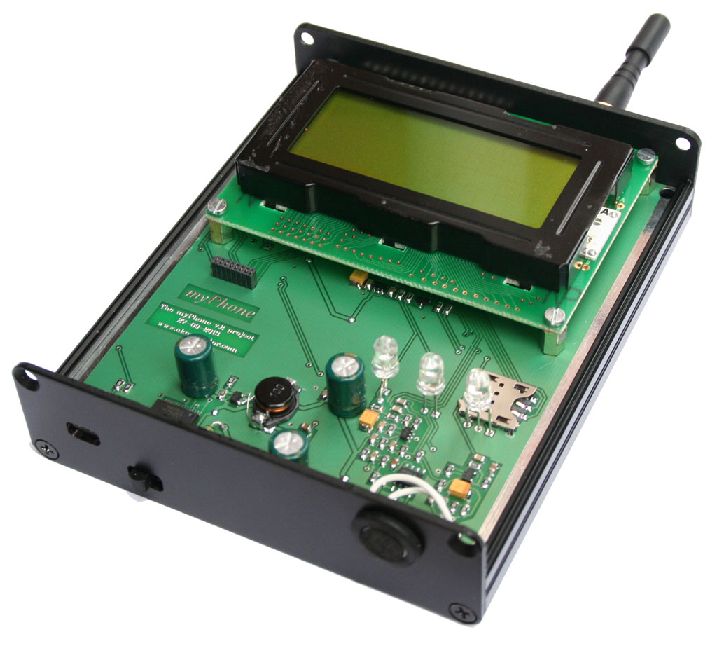
Enclosure
The metal enclosure is a Fischer AKG-105 (30 120 SA) black anodized aluminium body. I would like to thank the SeaSoft Ltd. who helped me in mechanical works to tool & shapen the enclosure based on my ideas. The PCB fits well in the middle of the enclosure. Below the PCB there is the speaker and there are two batteries to provide enough boost for chatting. There are holes drilled in the back shell to hear the crystal-clear sound (just kidding..) during calls. On the top there is the keyboard PCB and the foil keyboard glued to the top shell which has three holes for the LEDs, and a cutout for the LCD. The foil was produced by Elo-Tec Ltd. I would like to thank them the foil keyboard which were provided me as a gift in order to help me in my project. The microphone took place on the rear panel next to the power-switch.
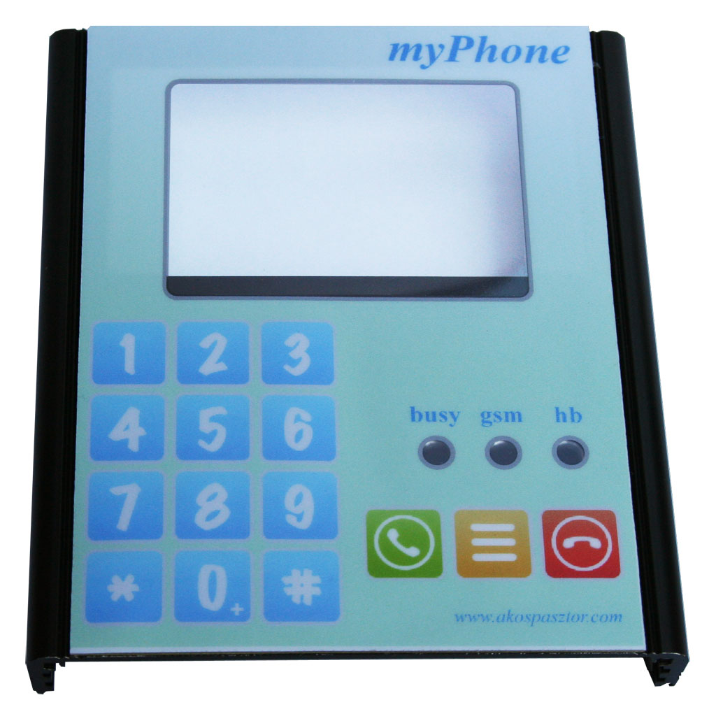
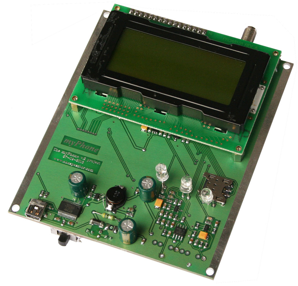
Assembled hardware
Here are some pics about the assembled hardware.

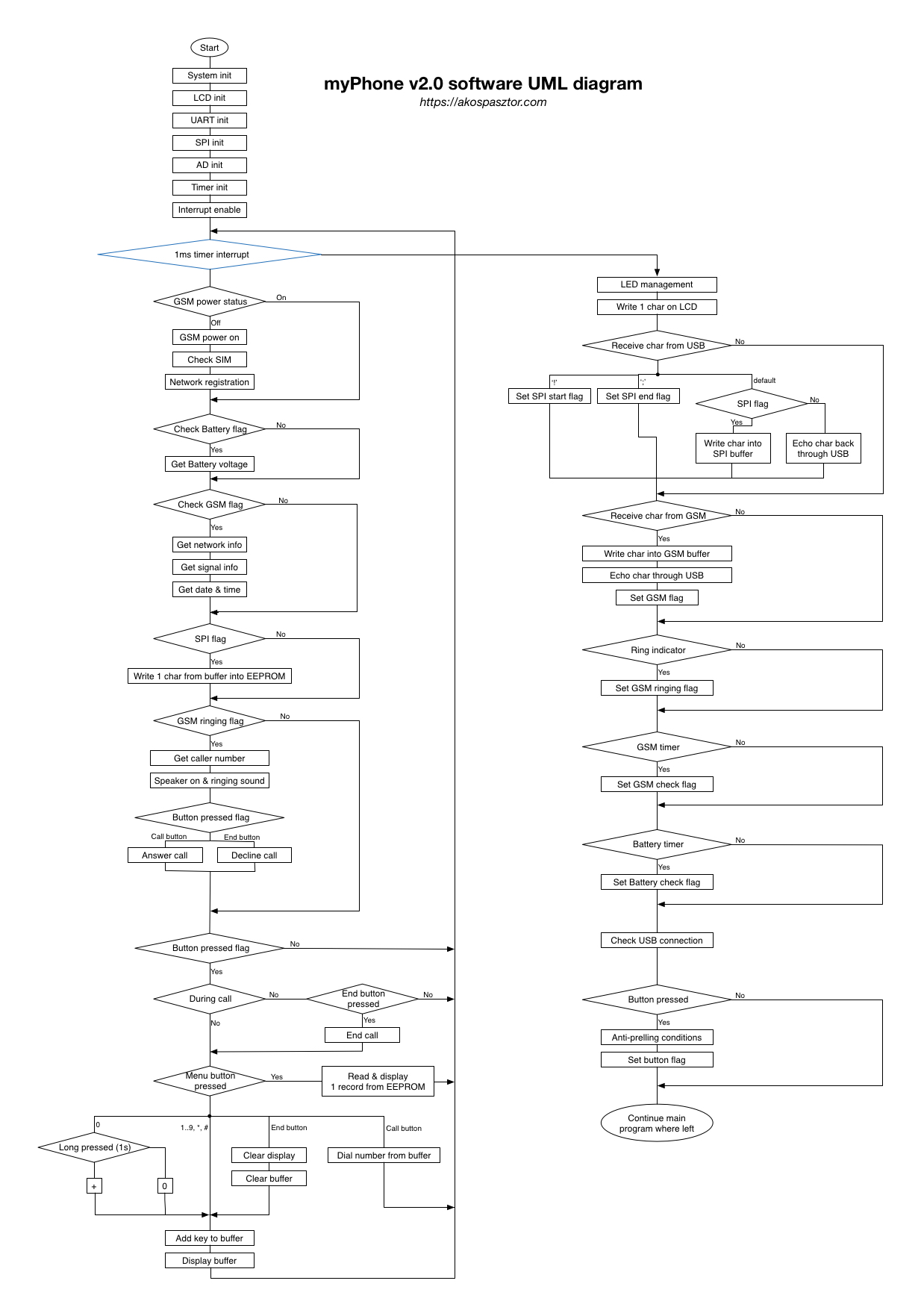
Software
I wrote the software in C language and used a JTAGICE mkII for programming & debugging.
Check out the source code on GitHub:
Block diagram
Note: You can download the block diagram as a PDF!
Video
Coming soon!