STM32 Circular DMA with Timeout
Overview
This example presents how to implement performance-efficient DMA timeout mechanism for peripheral DMA configured in circular mode. Read more, clone or fork the project at my GitHub repository:
Contents
Description
Implementing DMA for peripherals (e.g. UART) can significantly boost performance while reducing workload on the MCU (microcontroller) core [1], therefore configuring the DMA controller in circular mode can be straightforward for peripherals. However, in time-critical systems or hard real-time systems it is crucial to perform the required actions within specified deadlines. A DMA controller is only able to issue interrupts when its buffer is either full or halfway full, however considering UART communication, in most cases the received amount of data is not known in advance and the end of transfer cannot be detected. Consequently, when a transmission from a peripheral ends with a partially filled DMA buffer, and no further data is received over a certain period, a DMA timeout has to be implemented in order to process the remaining data. A DMA timeout means that a detectable event (e.g. interrupt) is generated when the following conditions are met: 1) DMA buffer is not full, and 2) no further data is received after a certain period.
ST suggests two methods for implementing DMA timeout in Section 2 of AN3019 [2]. The first method utilizes a timer in input capture mode. While this method is effective, it requires an available hardware timer and additional wiring. The second method requires no hardware changes and additional peripherals, instead it uses the system timer and utilizes the UART receive interrupt. The drawback of this method is that the UART interrupt service routine is called often during transmission, especially when the configured timeout period is short. This adds significant overhead to the system and affects performance and efficiency negatively.
In this demonstration, a more efficient idea is presented to implement DMA timeout. The UART peripheral can be configured to generate an interrupt when the UART module detects an idle line (end of transmission). After generating an idle line interrupt, it is not generated again until there is new data received. (For more information about how idle line detection and interrupt generation works, please refer to [3].) After detecting an idle line, a software timer is started with user-defined period. If no DMA transfer complete interrupt is generated within this period, a DMA timeout event is generated and new data in DMA buffer can be processed. This method provides an efficient way to implement DMA timeout and minimizing overhead by generating a single additional interrupt (UART idle line interrupt) after the end of transmission.
Implementation
The method is implemented and demonstrated on a 32L476G Discovery [4] kit equipped with a STM32L476VG MCU [5]. The on-board ST-Link provides an USB VCP (Virtual COM Port) to UART interface for the microcontroller. The UART lines are connected to PD5 and PD6 pins of the MCU. The DMA controller is initialized to receive data from this UART line. In this demonstration, the USB peripheral of the MCU is initialized in CDC VCP mode, therefore the received data is forwarded back to the PC via USB. The demonstration software uses the official HAL library of ST [6] and is compiled with IAR EWARM.
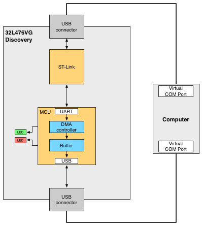
Figure 1: System overview
Source code organization
stm32-dma-uart/
  |—— Drivers/
  |—— EWARM/
  |—— Inc/
  |—— Middlewares/
  `—— Src/
Drivers and Middlewares folder contain the CMSIS, HAL libraries and USB
libraries for the microcontroller. The software source code and corresponding
header files can be found in Src and Inc folders respectively.
How it works
The DMA_Event_t structure type defined in main.h holds the required
variables for the DMA timeout implementation. The DMA buffer size and timeout
duration can be configured in main.h. When a UART idle interrupt occurs, the
timer is set to the configured duration and decreased in the SysTick interrupt
handler. After timeout, the flag is set and the DMA transfer complete callback
is executed. The prevCNDTR stores the previous value of the DMA CNDTR register
value, thus only the relevant, newly received data chunk can be extracted and
processed from the DMA buffer.
When a DMA transfer complete interrupt or DMA timeout occurs, the DMA transfer
complete callback is executed. Based on timeout state; current and previous
state of DMA (stored in the DMA_Event_t structure), the newly received data
(which can be the entire DMA buffer or only a part of it) is copied from the DMA
buffer to a new buffer. Then the data can be processed without being corrupted
or overwritten by further incoming data. In this demonstration the received data
is simply forwarded back to the computer via USB.
References
[1] Wikipedia, “Direct Memory Access”, https://en.wikipedia.org/wiki/Direct_memory_access
[2] AN3019, “Communication peripheral FIFO emulation with DMA and DMA timeout in STM32F10x microcontrollers”, http://www.st.com/resource/en/application_note/cd00256689.pdf
[3] RM0351, “STM32L4x5 and STM32L4x6 advanced ARM®-based 32-bit MCUs Reference Manual”, http://www.st.com/resource/en/reference_manual/dm00083560.pdf
[4] 32L476G Discovery, http://www.st.com/en/evaluation-tools/32l476gdiscovery.html
[5] STM32L476VG, http://www.st.com/en/microcontrollers/stm32l476vg.html
[6] UM1884, “Description of STM32L4 HAL and Low Layer drivers”, www.st.com/resource/en/user_manual/dm00173145.pdf